Following his PS4 Server 7.55 Project last month, PlayStation 4 Scene developer @stooged updated his Github repository with both a PS4 Server 9.00 and PS4 Server 9.00u (adds on / off switch for USB device) designed for the ESP8266 D1 Mini or the ESP8266 D1 Mini Pro to provide a WiFi HTTP server and DNS server for the recently released 9.00 Exploit for PS4 (9.00 Host Live Demo / GIT) consoles with a demonstration video below. 
Download: PS4-Server-900-main.zip / GIT / PS4-Server-900u-main.zip / GIT / firmware9dump.bin via @teginpeg / USB Fix.rar via @blumenal
From the PS4 Server 9.00 README.md file: PS4 Server 9.00
This is a project designed for the esp8266 D1 Mini or the esp8266 D1 Mini PRO to provide a wifi http server and dns server.
This is for the 9.00 exploit and the esp8266 device will handle sending the payloads to the binloader server in goldhen, the exploit has the mod by leeful to load goldhen automatically.
The firmware is updatable via http and the exploit files can be managed via http.
You can access the main page from the userguide or the consoles webbrowser.
Implemented internal pages
Make sure you set the flash size to match the D1 board you are using.
4M (3M SPIFFS) for the D1 Mini

There is a storage limitation of 2.8mb for the D1 Mini board.
16M (15M SPIFFS) for the D1 Mini PRO

There is a storage limitation of 14.2mb for the D1 Mini PRO board.
Next you connect to the wifi access point with a pc/laptop, PS4_WEB_AP is the default SSID and password is the default password.
Then use a webbrowser and goto http://10.1.1.1/admin.html 10.1.1.1 is the defult webserver ip.
On the side menu of the admin page select File Uploader and then click Select Files and locate the data folder inside the PS4_Server_900 folder in this repo and select all the files inside the data folder and click Upload Files you can then goto Config Editor and change the password for the wifi ap.
Alternatively you can upload the files to the esp8266 with the arduino ide by selecting Tools > ESP8266 Sketch Data Upload

The files uploaded using this method are found in the data folder inside the PS4_Server_900 folder.
 And from the PS4 Server 9.00u README.md file: PS4 Server 9.00u
This is a slight mod to PS4 Server 9.00.
I have added the ability to switch off and on the usb device by using the pin D7 on the board to trigger a relay to control the power to the usb device.
The idea is to cut the 5v power to the usb drive and have it switched on and off by a relay which is controlled by the esp8266 device and switch it off and on during the initial exploit load which removes the need to plug and unplug the usb drive.
Video
900u
You can make it with a usb A female to male cable, this is a basic diagram of how to set it up.
TRR1A05D00 5 Volt SPST DIL Reed Relay

BESTAR BR-500 Reed Relay (5V, 500Ω)

Another way to set it up is to use a npn transistor and cut the ground to the usb device which was shown by blumenal over on psxhax.
The parts required are:

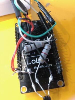
Fast and dirty, this is the test cable I made and this would be the easiest for people to make.
Parts used are:

This is the mod I did and the parts used are:


The end result:


The slim usb hub has less room but you should be able to fit the board in and use a reed relay to save a bit of space, I dont have a slim so I wont bother making this one but it is the same idea as the other mod.

The usb hub for the pro is still coming in the post and I will mod that one next.
Cheers to MSZ_MGS via Twitter for the heads-up on this earlier!

Download: PS4-Server-900-main.zip / GIT / PS4-Server-900u-main.zip / GIT / firmware9dump.bin via @teginpeg / USB Fix.rar via @blumenal
From the PS4 Server 9.00 README.md file: PS4 Server 9.00
This is a project designed for the esp8266 D1 Mini or the esp8266 D1 Mini PRO to provide a wifi http server and dns server.
This is for the 9.00 exploit and the esp8266 device will handle sending the payloads to the binloader server in goldhen, the exploit has the mod by leeful to load goldhen automatically.
The firmware is updatable via http and the exploit files can be managed via http.
You can access the main page from the userguide or the consoles webbrowser.
Implemented internal pages
- admin.html - the main landing page for administration.
- index.html - if no index.html is found the server will generate a simple index page and list the payloads automatically.
- info.html - provides information about the esp board.
- format.html - used to format the internal storage(SPIFFS) of the esp board.
- upload.html - used to upload files(html) to the esp board for the webserver.
- update.html - used to update the firmware on the esp board (fwupdate.bin).
- fileman.html - used to view / download / delete files on the internal storage of the esp board.
- config.html - used to configure wifi ap and ip settings.
- reboot.html - used to reboot the esp board
Make sure you set the flash size to match the D1 board you are using.
4M (3M SPIFFS) for the D1 Mini
16M (15M SPIFFS) for the D1 Mini PRO
Next you connect to the wifi access point with a pc/laptop, PS4_WEB_AP is the default SSID and password is the default password.
Then use a webbrowser and goto http://10.1.1.1/admin.html 10.1.1.1 is the defult webserver ip.
On the side menu of the admin page select File Uploader and then click Select Files and locate the data folder inside the PS4_Server_900 folder in this repo and select all the files inside the data folder and click Upload Files you can then goto Config Editor and change the password for the wifi ap.
Alternatively you can upload the files to the esp8266 with the arduino ide by selecting Tools > ESP8266 Sketch Data Upload
And from the PS4 Server 9.00u README.md file: PS4 Server 9.00uThis is a slight mod to PS4 Server 9.00.
I have added the ability to switch off and on the usb device by using the pin D7 on the board to trigger a relay to control the power to the usb device.
The idea is to cut the 5v power to the usb drive and have it switched on and off by a relay which is controlled by the esp8266 device and switch it off and on during the initial exploit load which removes the need to plug and unplug the usb drive.
Video
900u
You can make it with a usb A female to male cable, this is a basic diagram of how to set it up.
TRR1A05D00 5 Volt SPST DIL Reed Relay
The parts required are:
- 1k resistor
- 1.1k resistor
- BC 548 NPN transistor
Fast and dirty, this is the test cable I made and this would be the easiest for people to make.
Parts used are:
- D1 Mini Pro v1 ESP8266 board
- BESTAR BR-500 Reed Relay (5V, 500Ω)
- 0.5m USB 2.0 A Male to USB A Female
- D1 Mini Pro v1 ESP8266 board.
- PS4 USB HUB TP4-810
- TRR1A05D00 5 Volt SPST DIL Reed Relay.
- SanDisk Ultra Fit 8gb usb drive
- PS4 Slim USB HUB TP4-821
- BESTAR BR-500 Reed Relay (5V, 500Ω)
- D1 Mini Pro v1 ESP8266 board.
Cheers to MSZ_MGS via Twitter for the heads-up on this earlier!

")


") and with all the benefits of been on 9.0FW , it was just too much to not update the system. I loaded up the web page and it loads almost instant, I then load up Goldhen and it WORKS! Amazingly well... I am so Happy.
and with all the benefits of been on 9.0FW , it was just too much to not update the system. I loaded up the web page and it loads almost instant, I then load up Goldhen and it WORKS! Amazingly well... I am so Happy.